Page 9 of 22
Posted: Mon Apr 13, 2009 11:41 pm
by Smithers
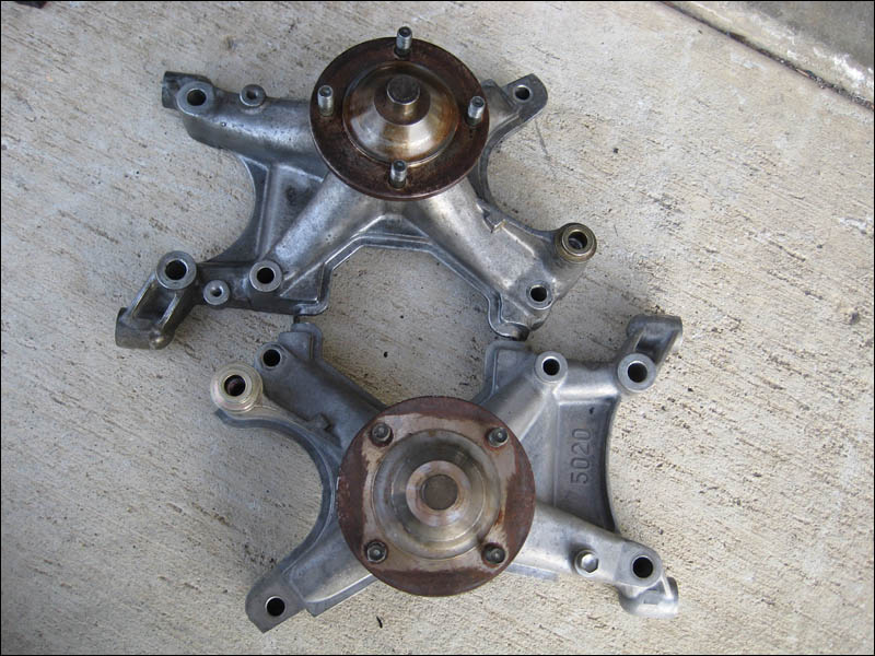
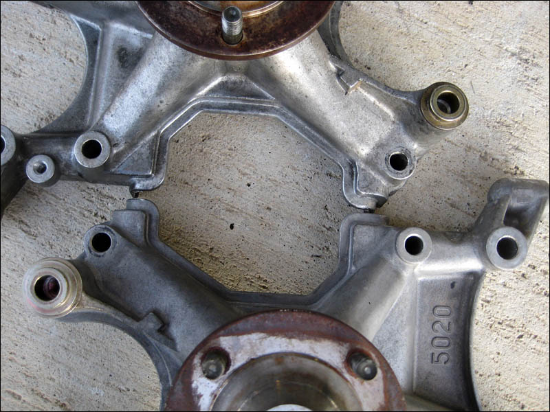
Now a big issue with the 1UZ-FE engine is that they use a special hydraulic pump that is located on the front of the engine in the bracket/pulley that you see on the driver side. In my pictures I already am showing the dummy idler that replaces the Lexus hydraulic pump. The Lexus pump only works with the Lexus power steering as it's quite complicated. So you need to get a dummy idler from a Toyota Sequioa or Tundra 2UZ engine.
Posted: Mon Apr 13, 2009 11:41 pm
by Smithers
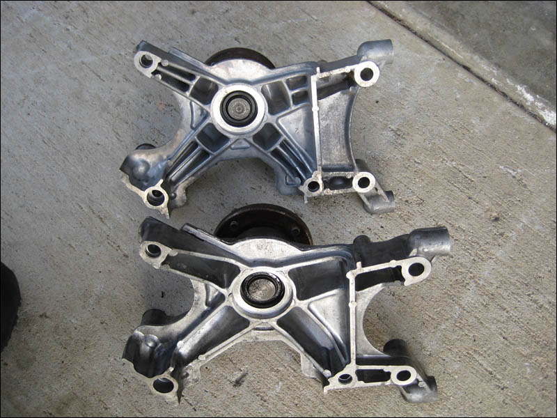
Now here's where the only differences come into view. Looking a little closer you can see the slightly wider mouth of the 2UZ edge. If you machine (cut) it off at the end it wouldn't even matter but as it is the plastic front engine covers won't fit as nicely. If you just left it loose and not tight fitting you might get some dirt in there in the long run but it's not a big problem, I recommend cutting the covers to make em fit snug, no big deal.
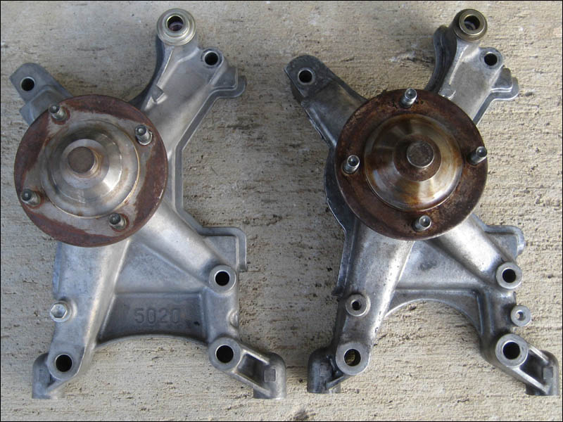 I almost went and trimmed them down but I took a look through my spare parts to find the correct idler pulley.
Posted: Mon Apr 13, 2009 11:48 pm
by Smithers
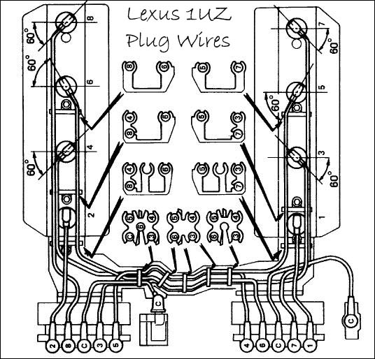
Now for the fun part... assembling the whole harness for the spark plug wires. It's a serious job as they fit together in a special configuration that must be done correctly. I'll show a diagram for the spark plug wires below.
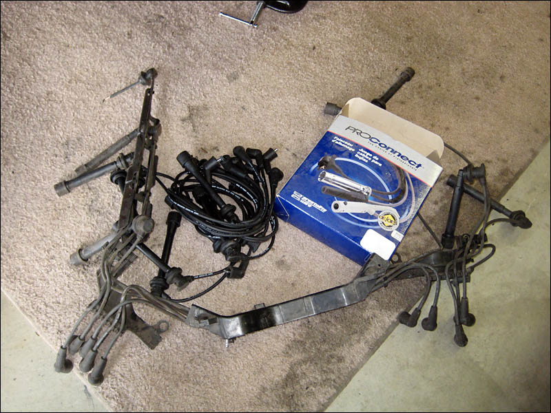
Here we go. Some fresh plug wires coming right up.
Posted: Mon Apr 13, 2009 11:55 pm
by Smithers
Ok here is the configuration for the 1UZ-FE spark plug wires. It's easy to follow but boy if you don't have a diagram to follow it's IMPOSSIBLE.
And here I have 3 sets of wires I'm playing with. I had to find the better of the two sets of plastic parts that are used to hold the wires in place on top of the engine.
Posted: Mon Apr 13, 2009 11:58 pm
by Smithers
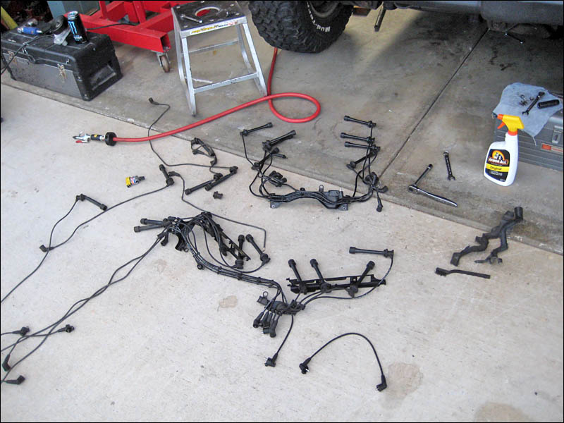
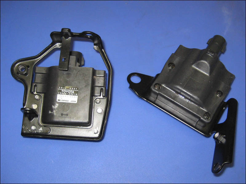
And prepping the coils for installation. These go on towards the end once you have the plugs installed and plugged into the distributor. But for now I located them and cleaned them up and put them in their powder coated brackets. I clean and coat everything mainly for corrosion resistance. I make sure and paint or spray WD-40 type oil on things as they will last much longer and when I go back to work on the engine everything will come apart much easier.
These brackets and coils were so corroded when I got them it was crazy. They looked like they were rusted together, ok they basically were. Now they are coated and will never look so bad again.
Posted: Tue Apr 14, 2009 12:04 am
by Smithers
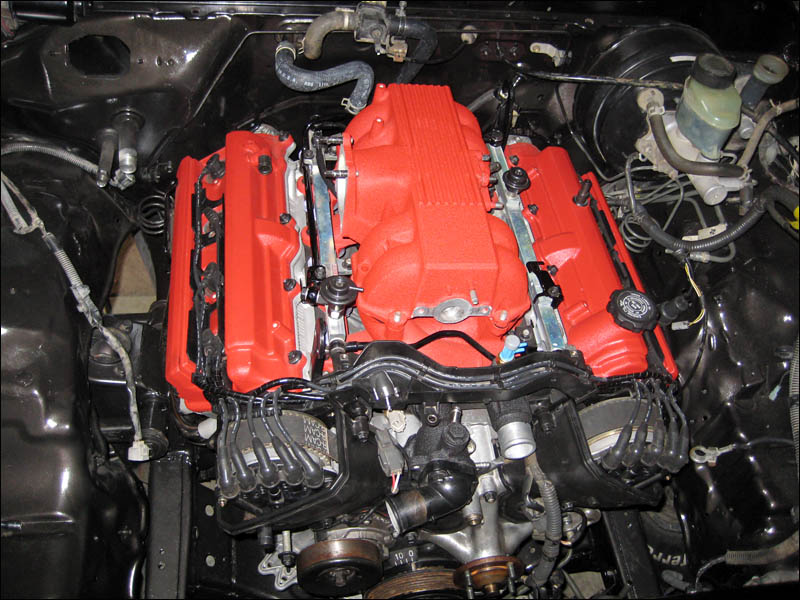
And finally I'm pretty excited to be finally assembling things. It actually looks like a finished engine almost. I wanted to take some pictures without the plug wire covers just to show how neatly tucked in they have it engineered. Pretty neat but it's harder on the wires. More heat is retained under the covers than I prefer but it's not that big of a deal to me since my engine will have much more air flowing under the hood than any Lexus car.

Posted: Tue Apr 14, 2009 12:05 am
by Smithers
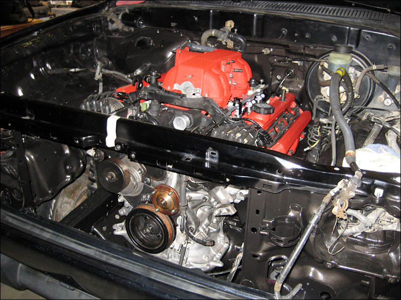
And a picture standing back a bit. It's actually feeling much closer to firing it up now.
Posted: Tue Apr 14, 2009 12:10 am
by Smithers
Tomorrow I'll be finishing up the engine covers then loosely fitting the AC and power steering units on the engine.
- The power steering lines will be routed and connected
- The vacuum lines and evap box
- Then pumping up the hydraulic throwout since I will be picking up fluid for it in the morning
- Then on to the wiring harness!!

- And finally the radiator will need to be fitted.
Posted: Sun Apr 19, 2009 9:58 pm
by Smithers
So where did I leave off? Ahh yes the water lines. You see on this 1UZ-FE engine they routed some simple water lines that go from one side of the rear water bridge all around the engine and then back into the other side of the water bridge. It's that simple. The coolant isn't necessarily pushed through these lines by a pump but the flow of the whole system just circulates it nonetheless.
The rear waterbridge between both banks of cylinders. Two large nipples for the heater core and two small ones that make the lap around the intake manifold for emissions controls.
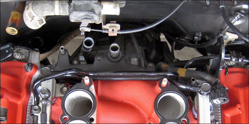
I'll just start from left to right with the flow of this water circuit. The water goes from the rear water bridge to the EGR and smog air outlet on the intake manifold. It merely passes through the air outlet as to bring it up to temperature quicker. By design all of the EGR system is brought up to operating temp as fast as possible to be effective as quickly as possible. So the coolant goes through the U.S. spec intake manifold EGR passageway and then on to the Idle Speed Control Valve or ISCV. This is so that the ISCV is warmed up quickly so that the engine runs properly as quickly as possible. If you happen to leave the hood up in a blizzard this would also help thaw out the ISCV upon firing up the engine.
 Here is the Idle Speed Control Valve - and the 3 obvious water lines:
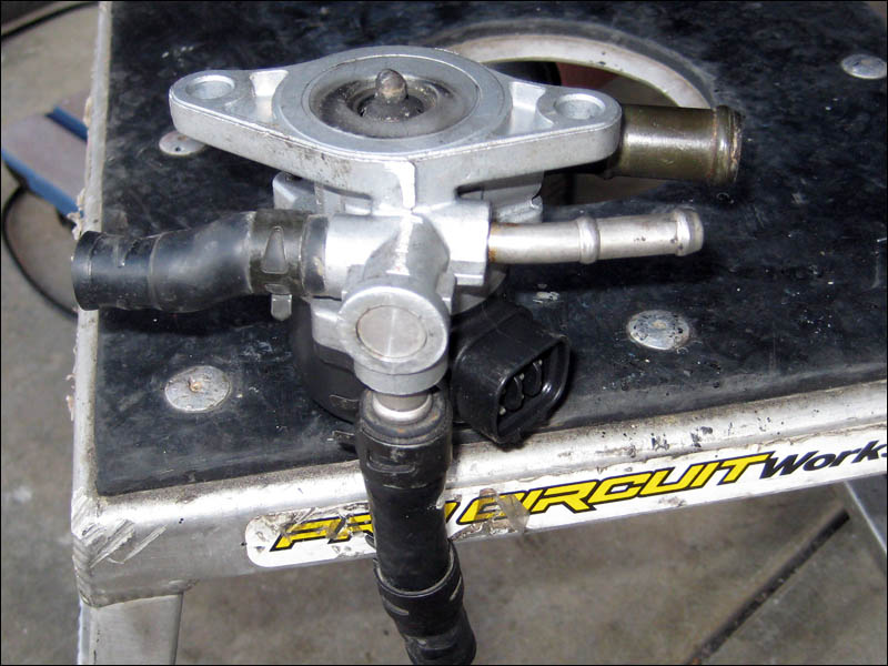
Then the coolant goes to the throttle body for much of the same reasons that I just listed for the ISCV. The biggest problem I have with this whole route for the coolant is that the throttle body is heated up to be much warmer than we want. Of course we want the air going into the engine to be as cool as possible to we will not be allowing coolant to complete this circuit. It would normally go through the throttle body and then complete it's journey to the left side of the rear water bridge.
Of the two coolant nipples exiting the water bridge I blocked off the one on the left of the engine. The one of the right I will connect with a coolant line that will go to the ISCV and then to the front water neck. Oh did I mention that there is also a short water coolant line from the front water neck (that contains the thermostat) to the ISCV? So that will work perfect. I don't mind running coolant to the ISCV. I want my idle working perfectly so if the engineers at Lexus decided that it would be good to preheat the ISCV then I'm on their side on this one. Maybe it works better when it's warm.

That also makes it easy on me. Blocking off the rear water bridge hose connections is a pain in the butt. I tapped and drilled the left side one but I would rather not do this to both of them. What happens when I put a Turbo on my engine and I need a coolant line?

So I'll leave the right side one alone and hook it to the ISCV and then have it exit to the water neck. This also makes it easier at the front of the engine since I only have to block one of the coolant lines on the ISCV - instead of 3. I'll put a bolt in the one I want to block off and then weld it in there carefully. Ok that's all done.
Posted: Sun Apr 19, 2009 10:18 pm
by Smithers
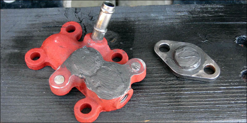
I also had to block off my EGR passageways. I had been putting this off because I wanted to make some nice little plates to do this. But I'm growing impatient and I don't want to spend a whole day making some trick plates. I just grabbed the parts and welded them shut then put RTV Black on the inside and out. The welding really shut them down and the RTV Black takes care of any dumb little pinholes and makes em look nice. Then I painted them but this picture was taken before that. Heck, it will work. The little one goes on the back of the intake manifold of course.
Posted: Sun Apr 19, 2009 10:29 pm
by Smithers
Let's move onto some wiring shall we? I have a few wiring harnesses but I broke out the one that was cut from the wrecking yard. I didn't think I would use it but it's not in bad shape at all so I started to take it apart. You can obviously see it was cut at the firewall. I have a wiring loom for the Adaptronic that is plenty long to this won't be a problem wiring the length since the 1UZ harness was cut.
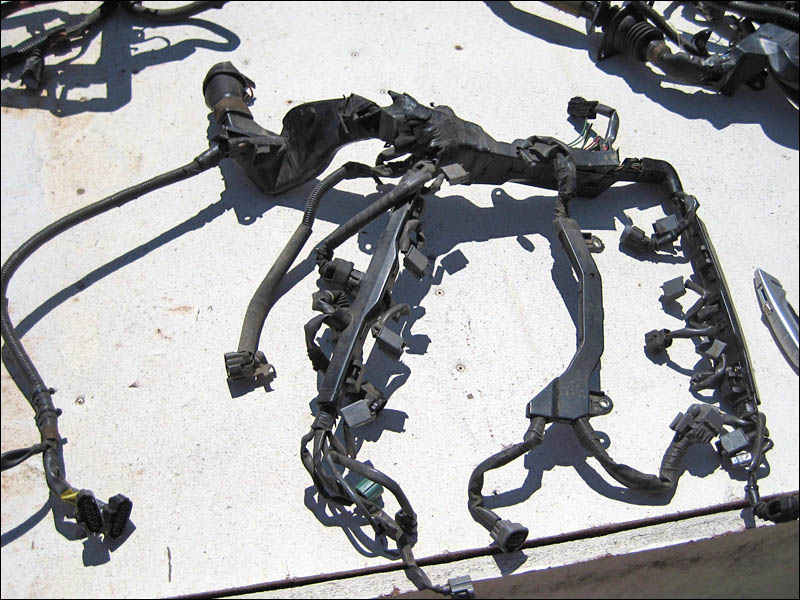
I started to unwrap it and take out some wires that I wouldn't be needing like the diagnosis terminal and a few others.
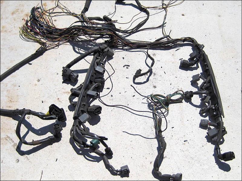
The ISCV connector and some wire can be seen in the bottom center almost completely separate from the main harness. It will be wired into the auxiliary circuit of the wiring loom to the Adaptronic. The Adaptronic is surely capable of utilizing the 1UZ ISCV to operate the engine properly. The only wire that I left connected to this connector was the ground. The remaining 4 wires connect to the Adaptronic.
Posted: Sun Apr 19, 2009 10:36 pm
by Smithers
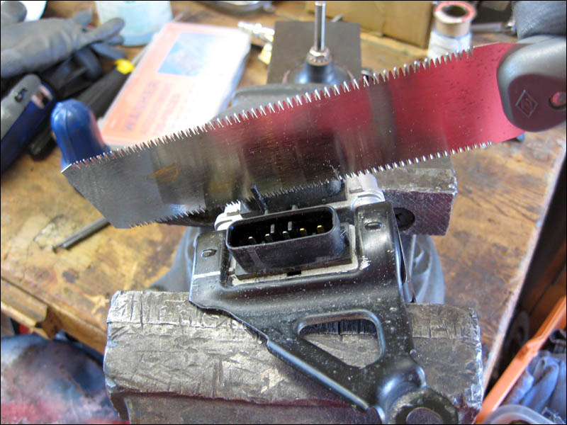
I scored a set of ignitors from an SC400. Since the person that sent me my engine didn't bother to include the LS400 ignitors I had to search for a while. People want a lot of $ for them and I eventually found a deal on some SC ignitors. Toyota/Lexus uses these types of ignitors in just about every single one of the 90's era vehicles. I KNEw that the SC ignitors would work for the 1UZ. Hell I even checked the part numbers from the ignitors with the ignitor for my 3RZ engine. Yep, same one.
Of course I double checked the wiring schematics to confirm the PIN arrangements. Yep, same pinout. So I just trimmed off this tab that they molded into the SC ignitor connectors. They do this just to scare people into thinking that they are different. They probably make a lot more money making the parts slightly different so they aren't interchangeable.
PRESTO! SC400 1UZ-FE ignitors now will work in the LS400 wiring harness! Amazing! haha
Posted: Sun Apr 19, 2009 10:41 pm
by Smithers
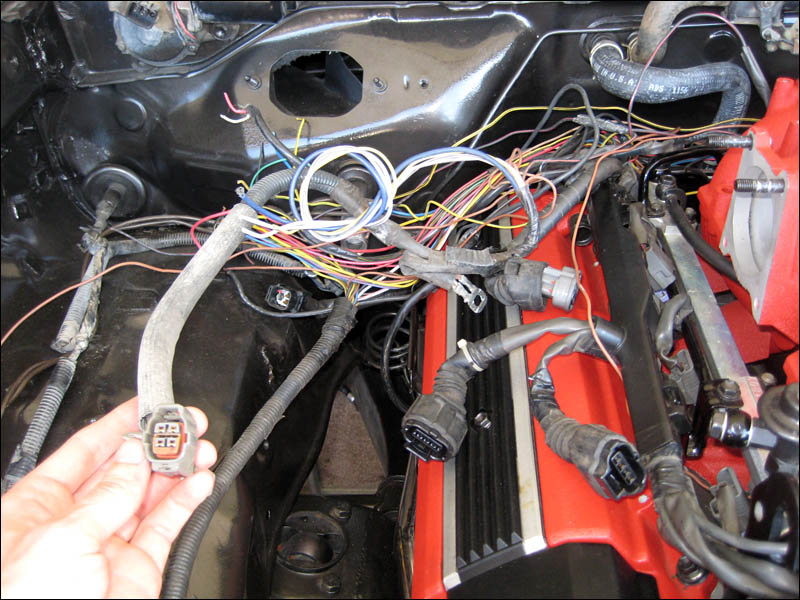
And moving on with some more wiring. The stock harness is wrapped for electric static shielding/ ESD as well as heat shielding. Why not use it? Plus it's already conformed to wrap around the engine just where I want it. I wasn't about to re-invent the wheel and custom wire the fuel injector harness. I can simple strip down the wires I need and run the tail ends to splice them into the Adaptronic wiring harness. I will the run them into the cab and plug them into the ECU that will be tucked nicely under the dashboard.
Posted: Sun Apr 19, 2009 10:49 pm
by Smithers
As you can see time is flying by. I got sidetracked with motorcycles for the past couple days as the weather has been awesome. It feels like summer already.
Today I spent half a day working on mostly wiring. But to get started I wanted to attach a couple more parts to the engine that have been bothering me. The smaller idler pulley was found under a pile of spare parts but I couldn't find the bolt for it. I spent at least 20 minutes looking everywhere for it. When I looked closely at the pulley I could tell it wasn't some ordinary bolt... it has a larger shoulder on it than the threads themselves are. Both of the engines that were brought to me didn't have the pulley installed so I didn't know what I was looking for besides pictures I have seen on the internet. I eventually found it and I'm warning everyone... Don't lose this sucker! Put it in a bag with the pulley itself just to make sure. This is one special little bolt here.
Posted: Fri Apr 24, 2009 9:42 pm
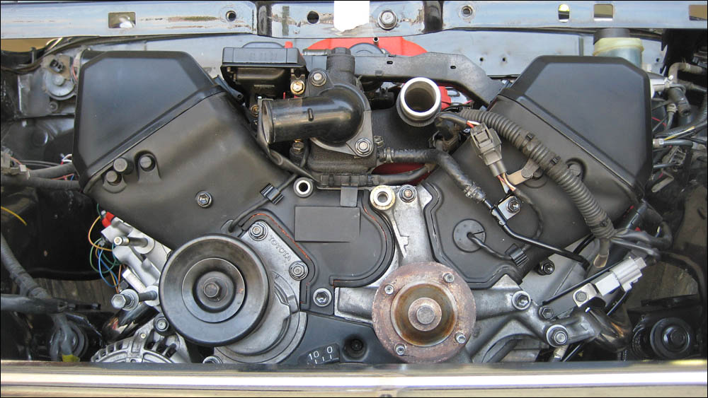
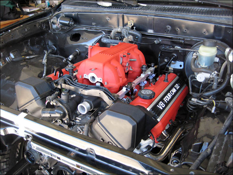
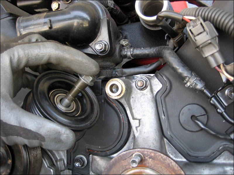
by Smithers
I was looking around for a good picture of the front of the 1UZ engine for reference but I never found a good one. So here is a shot of the upper front half of my engine so people can see the details. I'm just missing a long bolt that goes just under the water pump inlet as you can see. And right next to it is the hole that the small idler pulley bolts up to.